USER GUIDE
Global Edge User Guide
Instructions to help you BUILD YOUR NETWORK
Simple to follow instructions to help you build your empire

This user guide has been created to help Global Edge customers step by step as they research, configure and provision their network. Click on the tabs to navigate the user guide. For additional support check out the Contact Us page.
This user guide will demonstrate how to register with Global Edge and create your own network organisation.
Step 1: Click on Global Edge registration ULR link: https://my.globaledge.network/#/globaledge-register
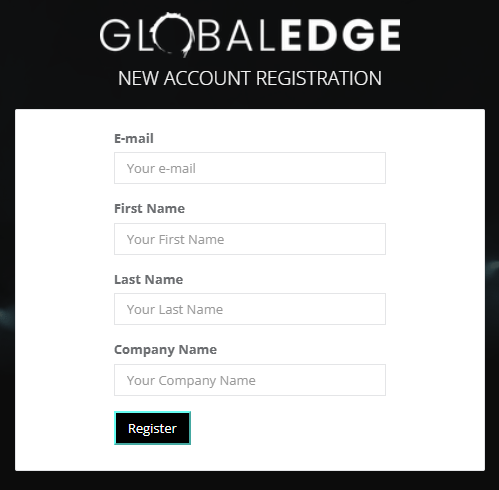
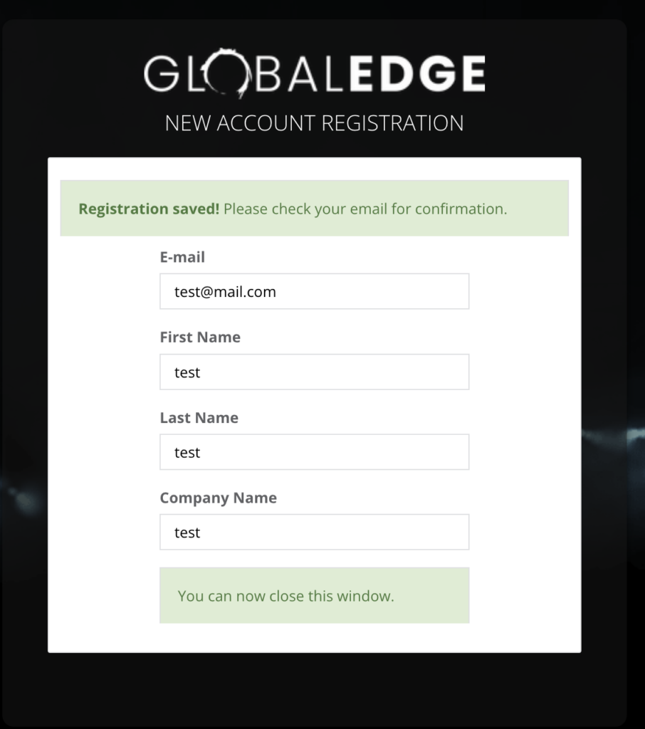
Step 2: A new page appears after registered.
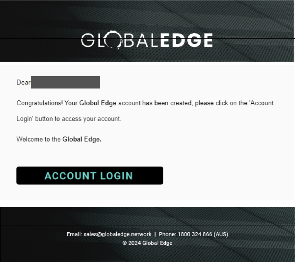
You will receive a Global Edge welcome email. Click the “Account Login” to proceed.
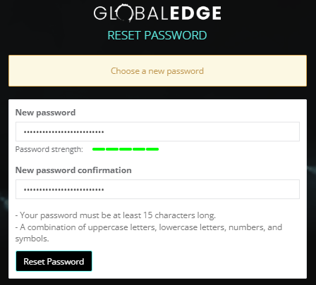
Step 3: Enter the new password. Your password must be at least 15 characters long. A combination of uppercase letters, lowercase letters, numbers, and symbols. Click “Reset Password” when the password strength is full green.
Step 4: You will receive a password reset confirmation. Click on “sign in” link.

Step 5: Please login with your username and password. Click “Login” button.
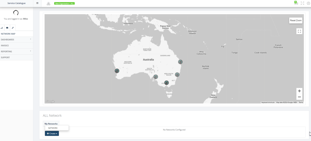
Step 6: You will login to Global Edge main page. Navigate the context tree to the Organisation All and scroll down the page to All Network and click “Create” and select “Network” to create the Tenant.
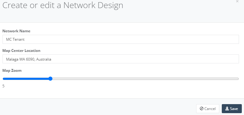
Step 7: A pop-up page will appear and allow you to enter the Network Name and location for the Tenant. Click “Save” button when done. Let’s use MC-Test-Rego and Sydney as an example.
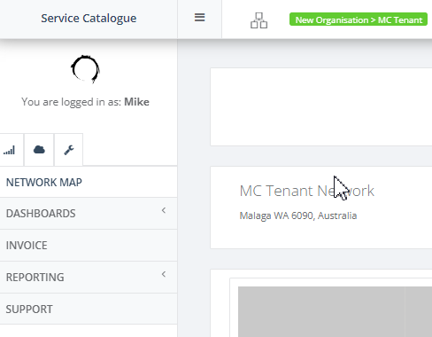
Step 8: The tree bar will confirm your organisation is created. You may proceed to create a new SD-WAN for your infrastructure.
This user guide will demonstrate how to create an NTU. View the YouTube Video.
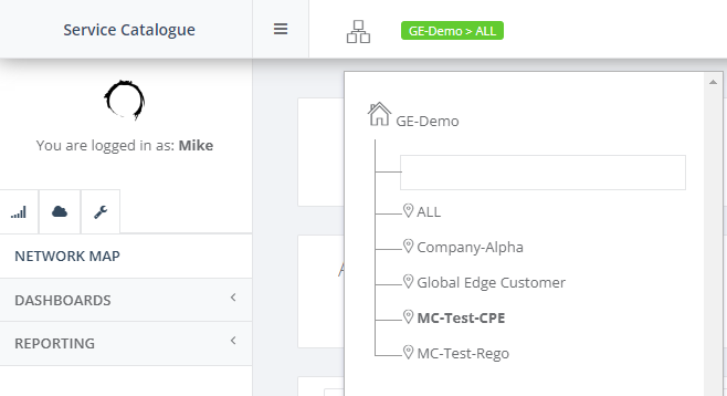
Step 1: After you have registered in Global Edge, navigate to your tenant. Let’s use the tenant MC-Test-CPE as an example.
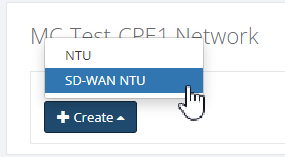
Step 2: Click “Create” and select “SD-WAN NTU” for first NTU at your nearest location (Perth, Adelaide, Melbourne, Sydney or Brisbane). Let’s use Perth as an example.
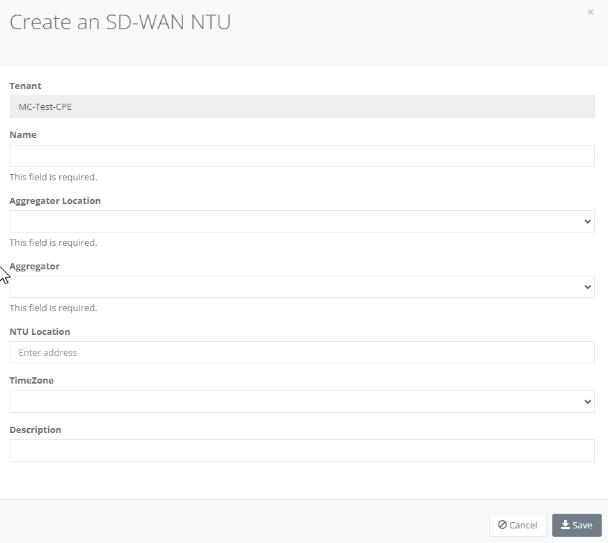
Step 3: Enter details in “Creates an SD-WAN NTU” and Click “Save”. All fields are mandatory.
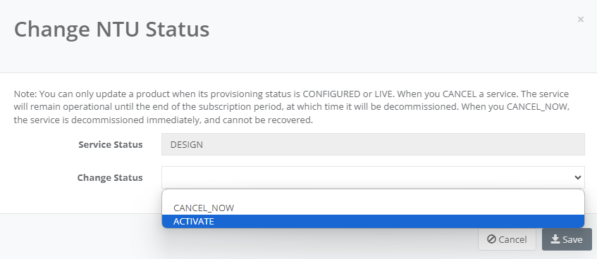
Step 4: Click the NTU “Action” and select “Change Status”.

Step 5: Select “Activate” in Change Status and click “Save”
Step 6: Click on the NTU “Actions” and select “SD-WAN Setup”

Step 7: On “Interface” Tab, enter the NTU interface type. Click “Add” button.
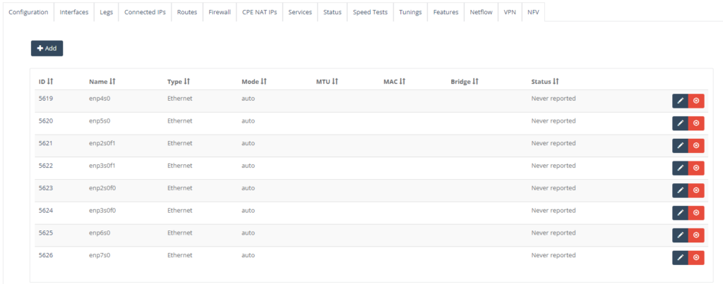
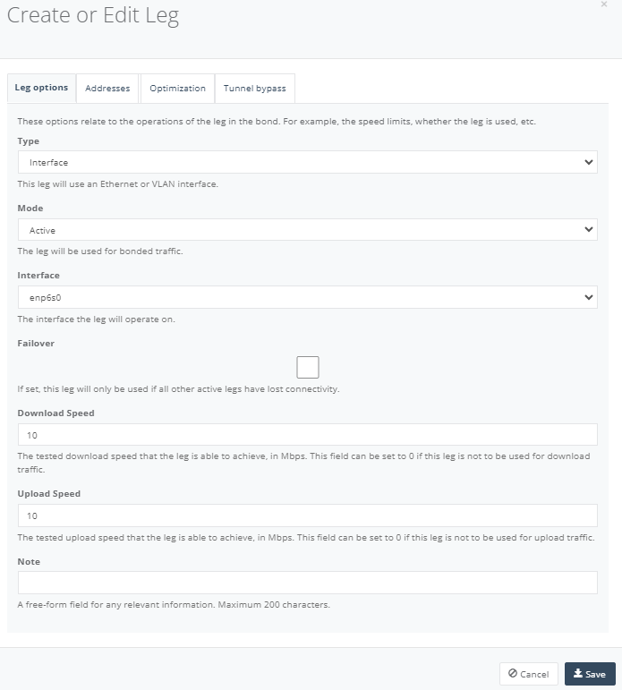
Step 8: On “Legs” Tab, enter the NTU WAN interface. Click “Add” button.

In “Leg Option” tab, enter the interface where it is connected to the carrier’s link.
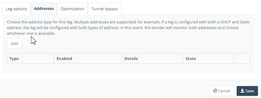
In “Address” Tab, click “Add” to configure the NTU WAN interface to DHCP to assign the WAN IP from the carrier’s link, provided the carrier’s link is set to DHCP as well.
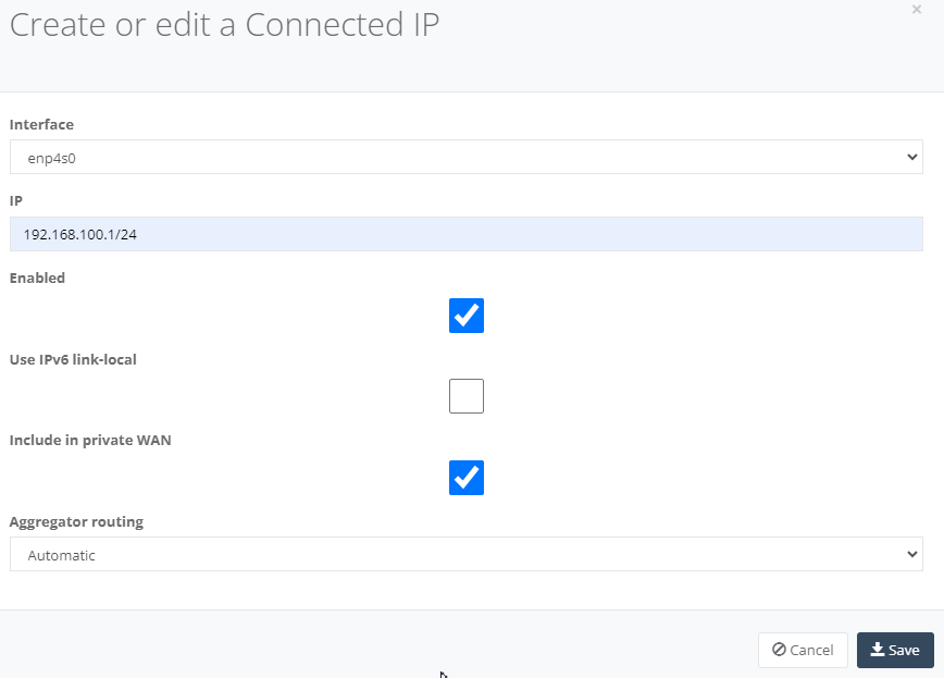
Step 9: On “Connected IPs” Tab, click “Add” to enter the NTU LAN interface.

Enter the Interface type for the LAN handoff, IP subnet and tick “Include in private WAN” box. Click “Save” to configure the setting.
Step 10: On “Services” Tab, enter the NTU LAN interface services to enable DHCP. Click “Add” and select “DHCP”.

On “Standard Configuration” tab, select the Connected IP for the LAN IP Subnet, DHCP as local and DHCP range start & end range.
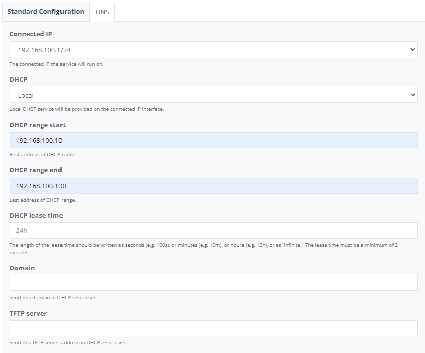
On “DNS” tab, enter the DNS Server1 & Server2 and click “Save”.
This user guide will demonstrate how to enable Netflow and SD-WAN traffic.
Step 1: After you have registered in Global Edge, navigate to your tenant. Let’s use the tenant MC-Test-CPE as an example.
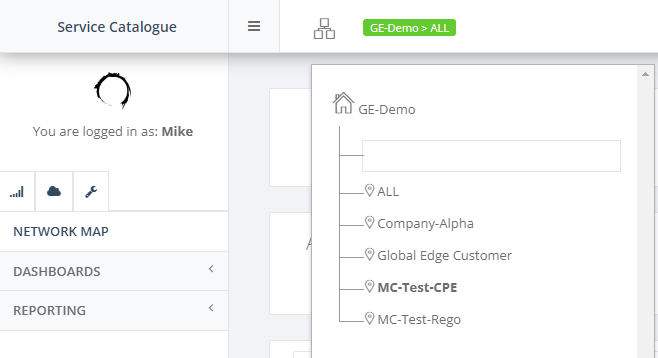
Step 2: Prerequisite you should have the NTU created and have the Interface, Legs, Connected IP and Services configuration configured. Let’s click on the NTU “SD-WAN Setup” to configure.

Step 3: When you have the NTU box online, check the Legs Status is Green.

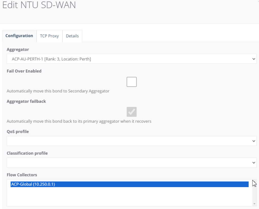
Step 4: On “Configuration” Tab, click on the “Edit” to enable Flow collectors.

Step 5: Under Flow Collectors, highlight “ACP-Global” and click “Save” to exit.
Step 6: On “Netflow” Tab, under Flow Collector drop down, select “ACP-Global” and click “Save” to exit.

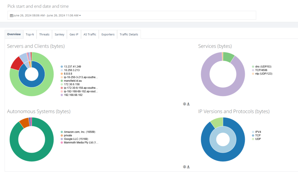
Step 7: Back on main menu, on NTU “Action” select Internet to view the SD-WAN traffic analytics.

Step 8: This shows the NTU SD-WAN traffic analytics.
This user guide will demonstrate how to activate & configure AppFlow Deep Packet Inspection (DPI) on your NTU.
Step 1: After you have registered in Global Edge, navigate to your tenant. Let’s use the tenant MC-Test-CPE as an example.
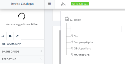
Step 2: Prerequisite – you should have the NTU created and have the Interfaces, Legs, Connected IP and Services configuration configured. Let’s click on the NTU “SD-WAN Setup” to configure.

Step 3: When you have the NTU box online, check the Legs Status is Green.

Step 4: On “Features” Tab, click on the return button to activate AppFlow.

Step 5: Once activated, a new “AppFlow” tab will appear.

Step 6: On “AppFlow” tab, click “Action” and select “Activate”.

Step 7: A pop-up page will appear. Click “Activate” to proceed. Give it a few minutes to finish installing AppFlow.
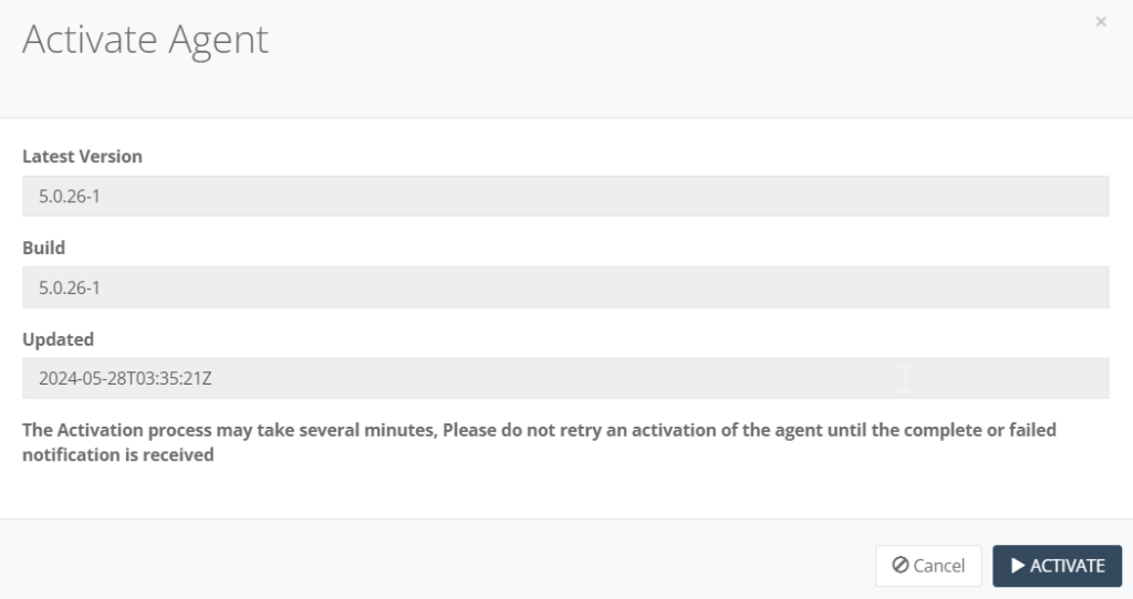
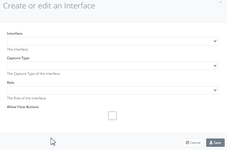
Step 8: Once finished installing, the page will appear a new Agent Interfaces. Click “Add” for the Agent can listen and analyse traffic. Enter the details of the new interface. Click “Save” when done.
- Select the interface to listen on
- Select the capture type (typically PCAP)
- Select the interface role (typically WAN)
- Select Allow Flow Actions and select the Flow Actions allowed on the interface (see below for more on Flow Actions)
Flow Actions are functions that can be run when selected Applications, Traffic Categories or Protocols are detected. Currently, the Flow Actions available are:
- BLOCK: use the NTU firewall to block traffic from traversing the interface.
Step 9: You may add any other interfaces required for analysis. Below is the example of the agent interfaces added.
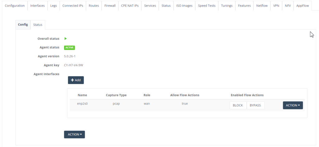
Step 10: Click “Block” under Enabled Flow Actions. A pop-up form is displayed to add an entry.
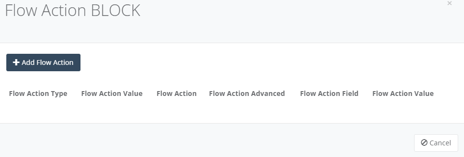
Step 11: Click “Add Flow Action” to add an entry. Click “Save” when completed.
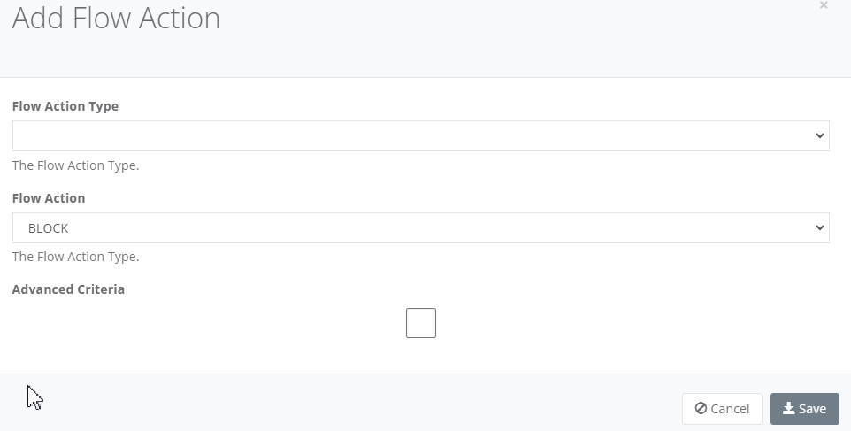
- Select the Flow Action type from Application, Category or Protocol. Once the Type is selected a new dropdown will be shown to select the value:
- Select the Flow Action from BLOCK
- Select Advance Criteria if you want to limit the detection to a specific Local IP Address, Local MAC Address or Other IP Address (typically destination IP).
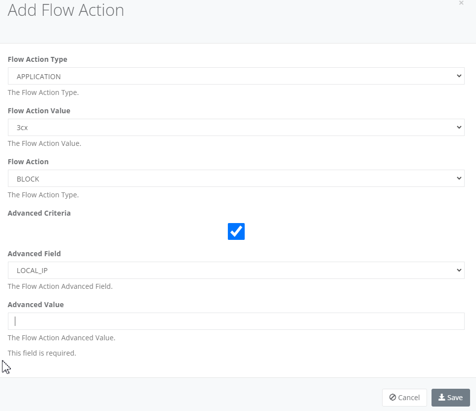
- Add the Flow Action Advanced value of the field i.e. an IP Address or MAC Address.
Step 12: You may review the Flow Action Block type. Click “Cancel” to exit the Flow Action.
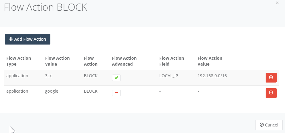
Step 13: Go back to main page and select the NTU and click “Actions” and select AppFlow to see the traffic analytics and details.

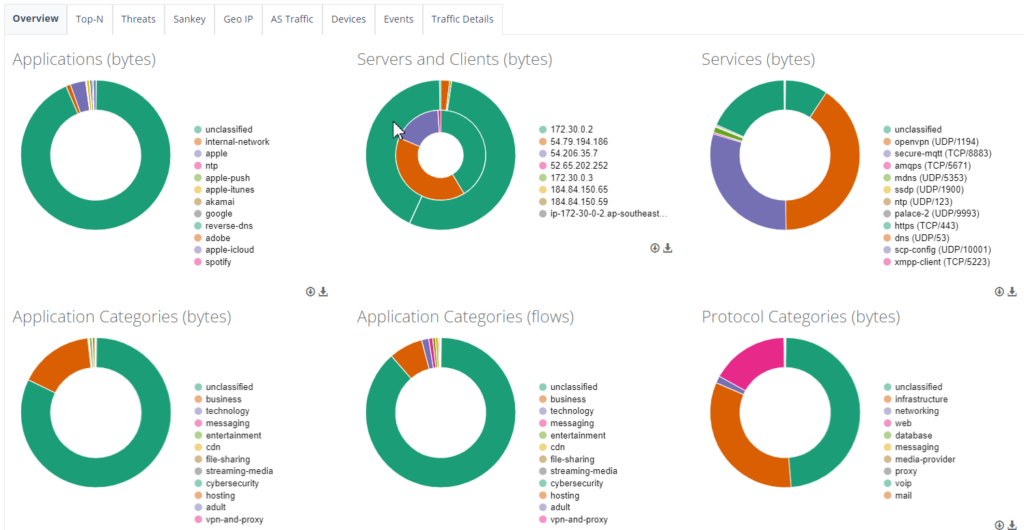
Sample of the AppFlow traffic analytics.
This user guide will demonstrate how to configure an NTU to your BYO Hardware Firewall.
Step 1: After you have registered in Global Edge, navigate to your tenant. Let’s use the tenant MC-Test-CPE as an example.
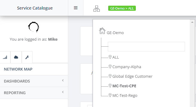
Step 2: Prerequisite you should have the NTU created, have the Interfaces, Legs, Connected IP, Services configuration configured and is connected to the Firewall gateway. Let’s click on the NTU “SD-WAN Setup” to configure.

Step 3: When you have the NTU box online, check the Legs Status is Green.

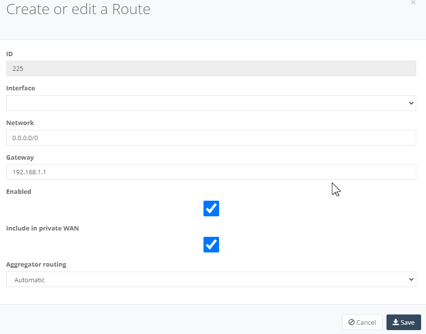
Step 4: On “Routes” Tab, enter default routes to ensure all traffic destined for outside your local network is to the Firewall gateway.

Click “Add” to create the route for Network, Gateway and tick “Include in Private WAN”. Click “Save” to exit.
Step 5: On your Firewall ensure you setup a “Static Routes” to enabling your local network can reach out to the Internet.
This user guide will demonstrate how to configure a virtual firewall on your NTU NFV.
Step 1: After you have registered in Global Edge, navigate to your tenant. Let’s use the tenant MC-Test-CPE as an example.
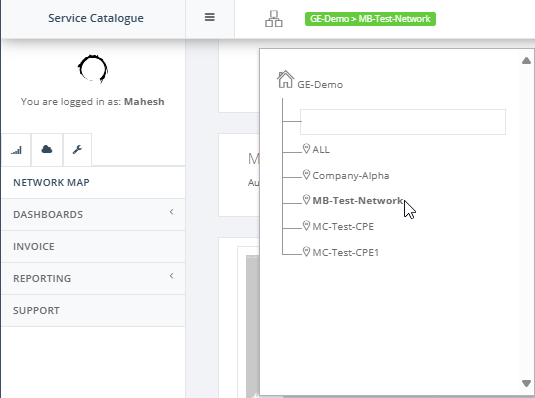
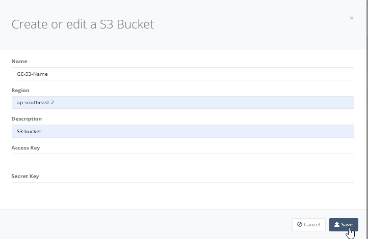
Step 2: Navigate the menu and select “NFV Bucket” and click “Create” S3 bucket.

Step 3: Enter all the fields which you have the S3 bucket details and click “Save” to exit.
Step 4: Prerequisite you should have the NTU created and have the Interface, Legs, Connected IP and Services configuration configured. Let’s click on the NTU “SD-WAN Setup” to configure.

Step 5: When you have the NTU box online, check the following is completed.
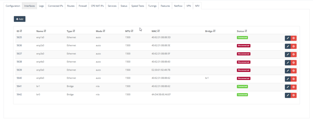
Configure NTU with necessary Interfaces and Legs. For instance:
• enp1s0 is the leg for SD-WAN bonding.
• enp5s0 used as passthrough which is the WAN interface on NFV (VNF Firewall).
• enp6s0 is bridged (service chain) to the LAN interface of the NFV (VNF Firewall) (via br1).
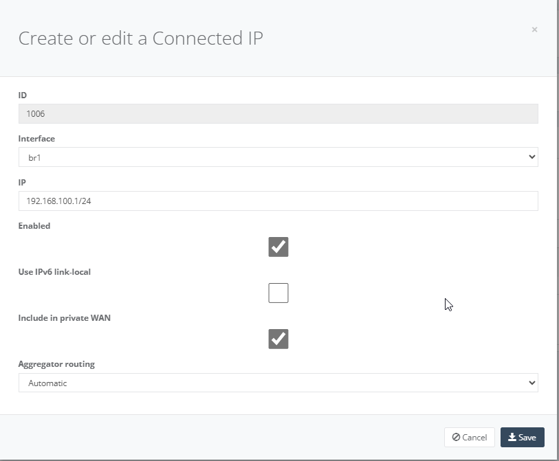
Step 6: On “Connected IP” Tab, click “Add” for interface “br1” to the VNF LAN side.

Click “Include Private WAN” and click “Save” to exit.
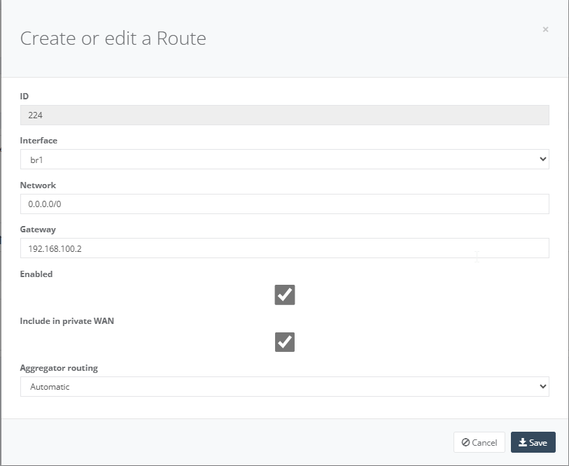
Step 7: On “Routes” tab, enter default routes to ensure all traffic destined for outside your local network is to the VNF Firewall gateway.

Click “Add” to create the route for bridge Interface, Network, Gateway and tick “Include in Private WAN”. Click “Save” to exit.
Step 8: On “NFV” Tab, click “Action” and select “Activate” NFV. Please note this may take up to 5mins to complete the NFV activation.

Step 9: Once the NFV Activation is completed, you will see two new tabs created. Click “Images” tab and “Add” to add the image from your S3 Bucket.

Step 10: Select the S3 Bucket you have added from NFV Bucket.
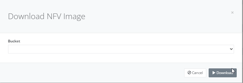
Step 11: On tab “Guests”, click “Add” button to install the VNF of your choice.

Step 12: Depending on your VNF size, select and enter the appropriate setting and click “Deploy”.
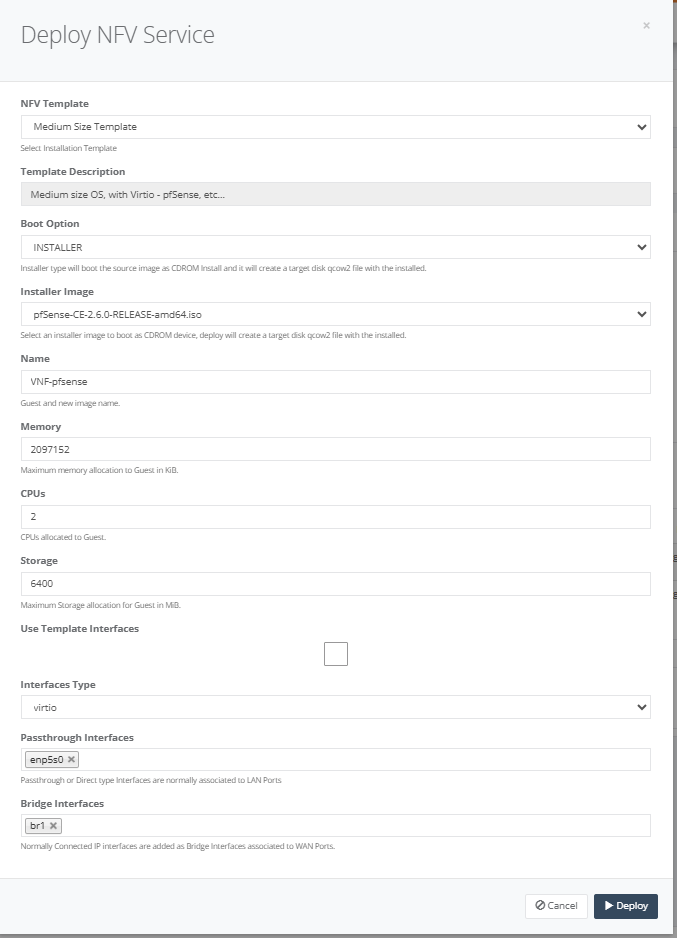
Several templates to assist you. For example, the VNF software use the medium sized template, which pre-defines the CPUs and memory allocation.
The boot option provides options to boot from either qcow or ISO files.
The passthrough interface was configured previously and refers to the LAN side of the CPE.
The bridge interface was configured previously and refers to the bridging interface between the VNF VM and the SD-WAN VM.
Step 13: After you deploy the service, a console window will pop-up to show you the status of the installation.
Step 14: Once the installation process has been completed use the console to configure the LAN side interface of the VNF software. The console link can be found by clicking on the name of the VNF. Click the “Console” tab and you can connect to the console of the VNF.

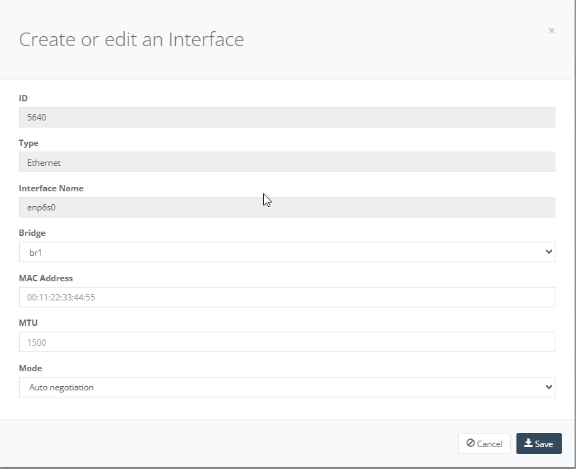
Step 15: On “Interface” tab, interface br1 (service chain) will show connected. Click Interface enp6s0 click “Edit” to link interface br1 to Bridge. Click “Save” to exit.
Step 16: On your VNF FW ensure you setup a “Static Routes” to enabling your local network can reach out to the Internet.
This user guide will demonstrate how to configure Managed Firewall for your NTU to reach the internet.
Each major state should have a dedicated managed Firewall.
Step 1: After you have registered in Global Edge, navigate to your tenant. Let’s use the tenant MC-Test-CPE as an example.
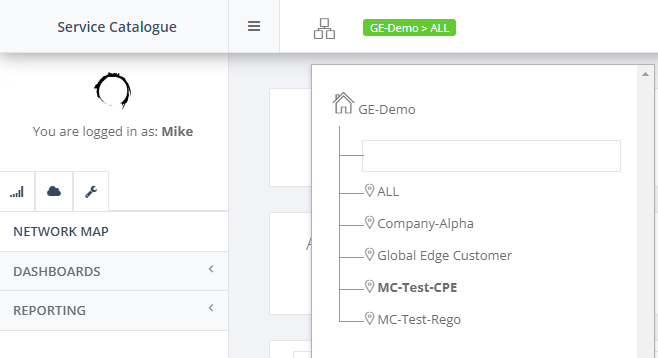
Step 2: Prerequisite you should have the NTU created with Interface, Legs, Connected IP and Services configuration configured. Ensure the NTU status is in Live stage. Let’s use Perth NTU as an example.

Step 3: Go to Network Map View and click on “Perth PoP” and select “Managed Firewall”.
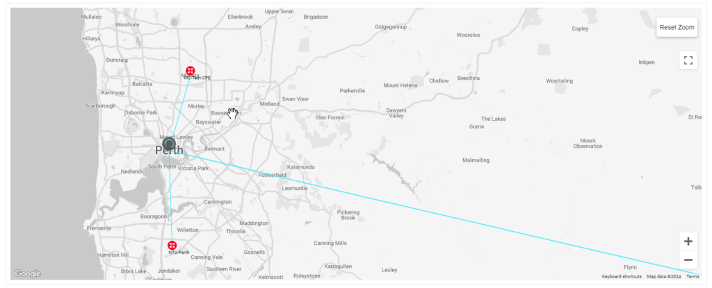
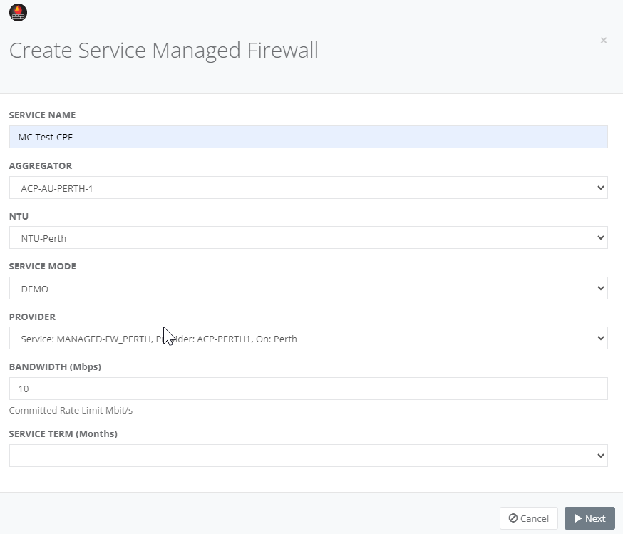
Step 4: Enter the fields for the NTU to the PoP, Service Mode, Bandwidth, term and click “Next”.
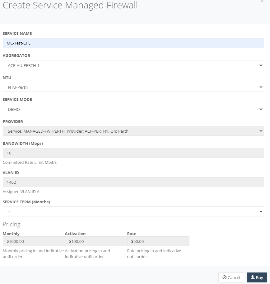
Step 5: The next page will validate configuration successfully, and you will see the pricing. Click “Buy” to purchase.
Step 6: Back to the main menu, on “Service” tab, you will see the Managed Firewall. Click the “Edit” to configure the Firewall Rules.

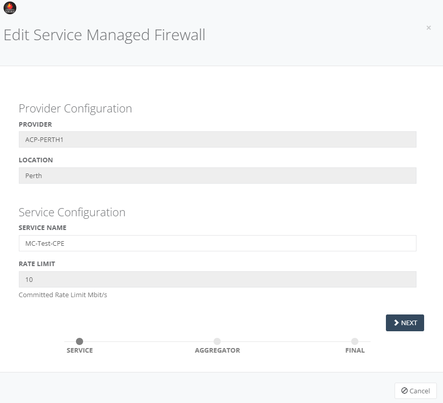
Step 7: Review the Provider Configuration and Service Configuration and click “Next”.
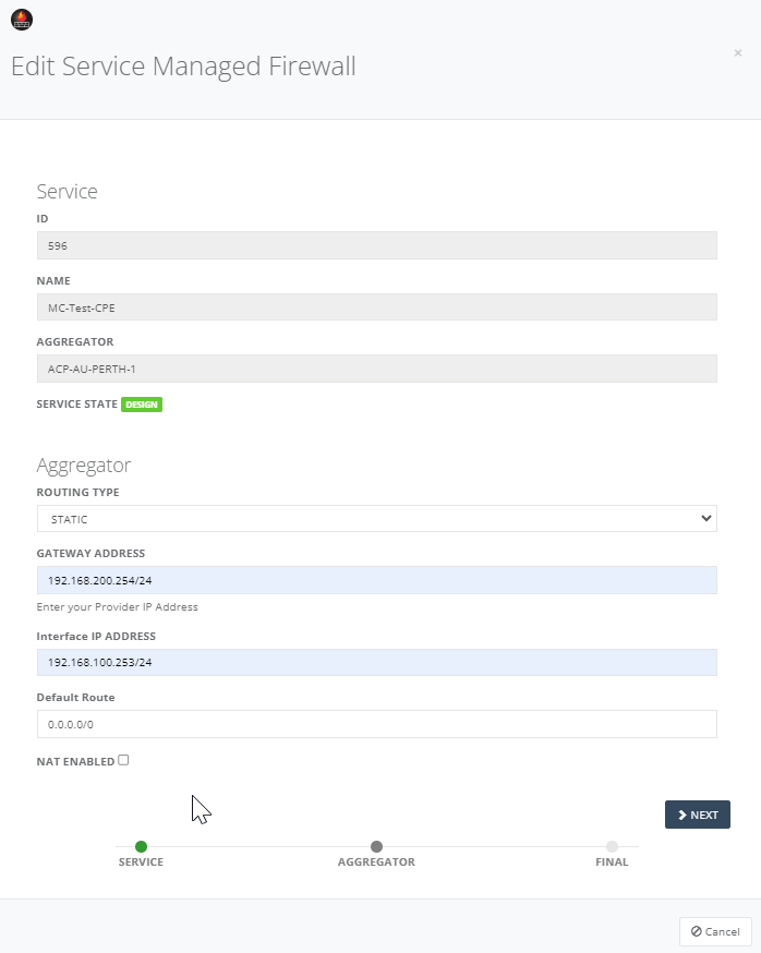
Step 8: Review the Service and configure Aggregator “Static” in Routing Type to update the field for Gateway Address, Interface IP, Default Route and NAT enabled where necessary. Click “Next” to continue.
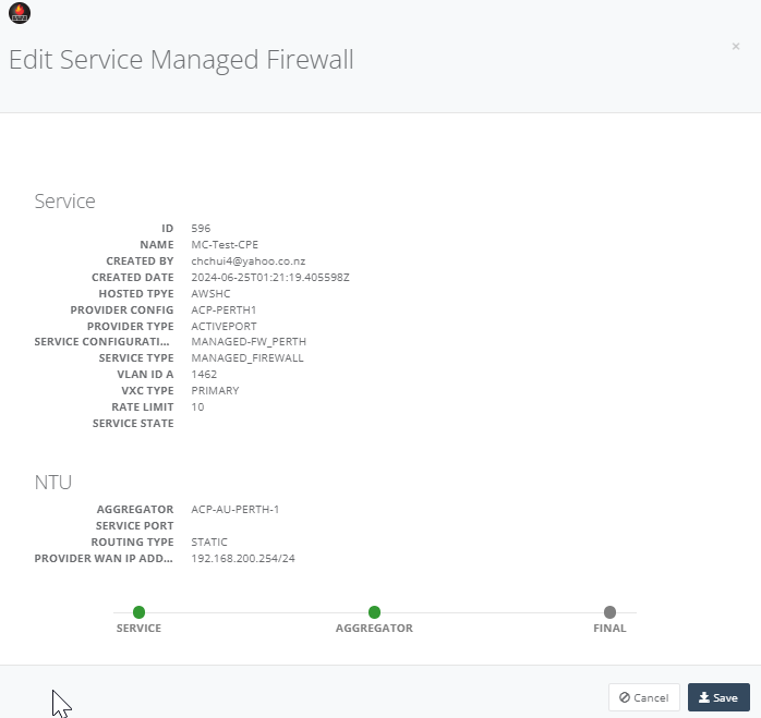
Step 9: Review the configuration summary and click “Save”.
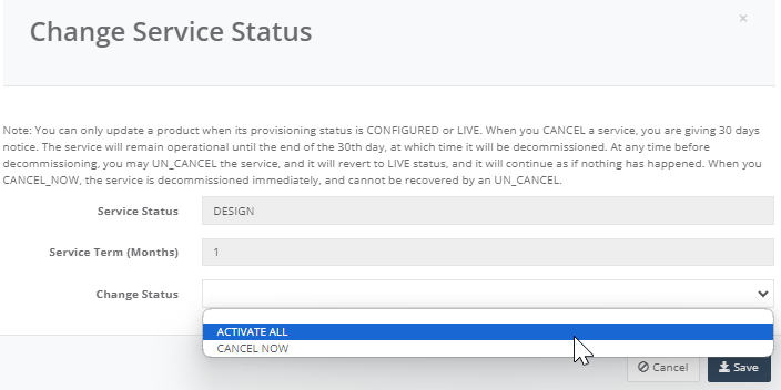
Step 10: Back to the main menu, on “Service” tab click on the service “Status” to activate all.

Step 11: Go to Change Status and select “Activate All”. Click “Save”.
Step 12: Back on the main menu, on “Service” tab click on the Managed Firewall to edit the firewall rules.

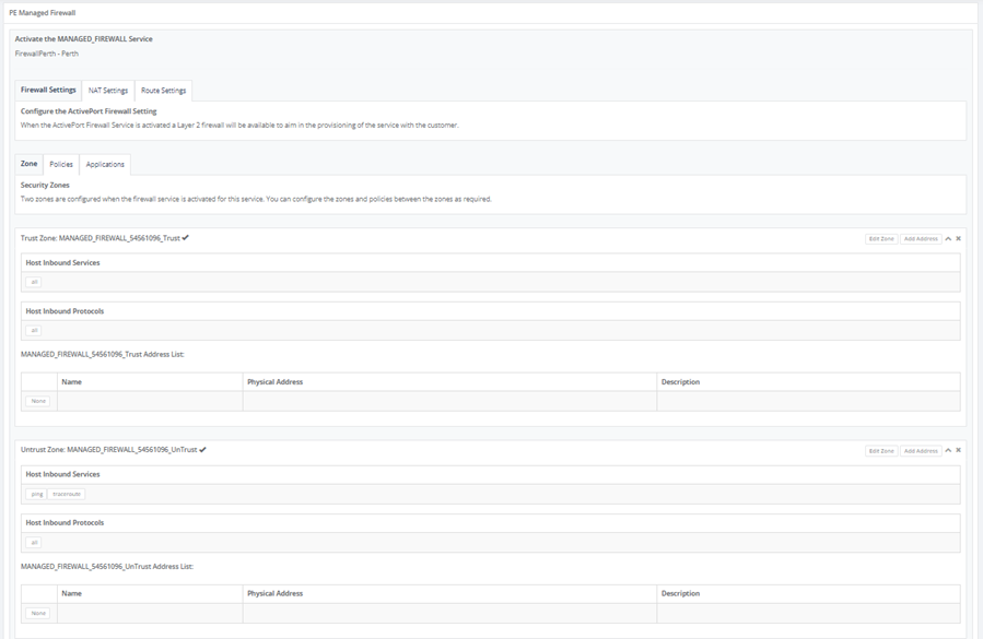
Step 13: PE managed firewall configuration is ready. Select “Firewall Setting”, “NAT Settings” and “Route Settings” tab to your preferences.
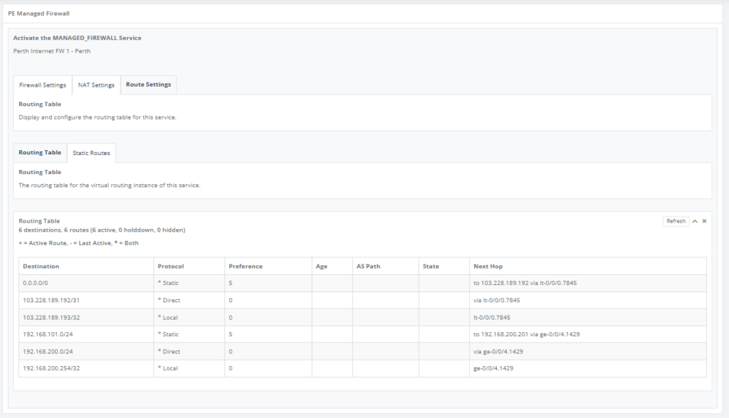
Step 14: Go to “Route Setting” and on “Route Table” Tab, this will show the contents of the service route table only.
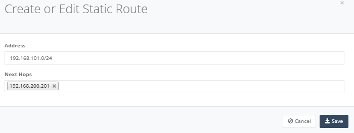
Step 15: Select “Static Routes” tab and click add “Route” to add the subnet for Connected IP, next hop field of the VLAN interface on the Managed FW. Click “Save” to exit.

After added the details, click “Save” to exit.
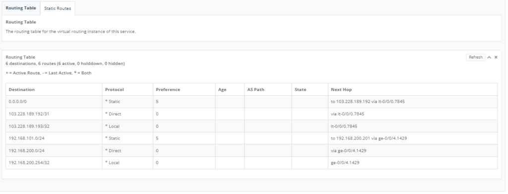
Once saved, traffic will start flowing and the route table will also reflect the change below:
Step 16: On the “NAT Setting” Tab, add the Connected IP of the NTU onto the NAT Source.
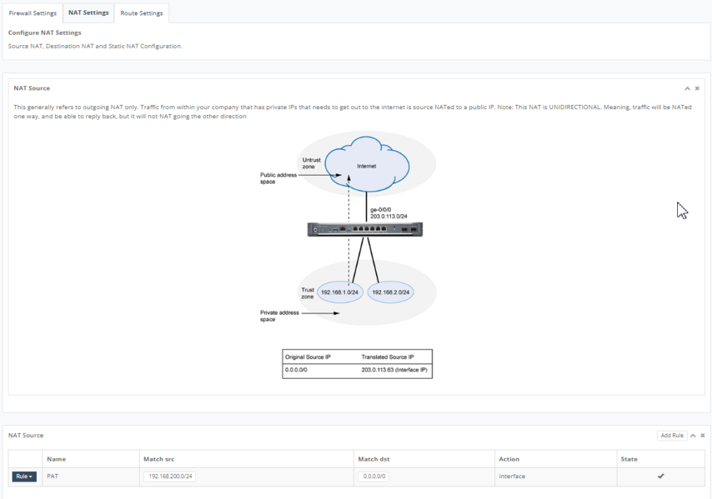
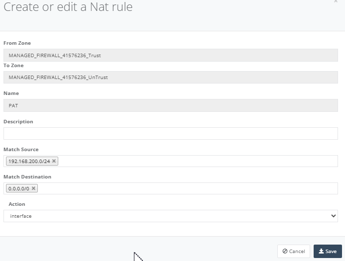
Click “Add Rule” to give it a name, add a source subnet and destination all. Click “Save” to exit.
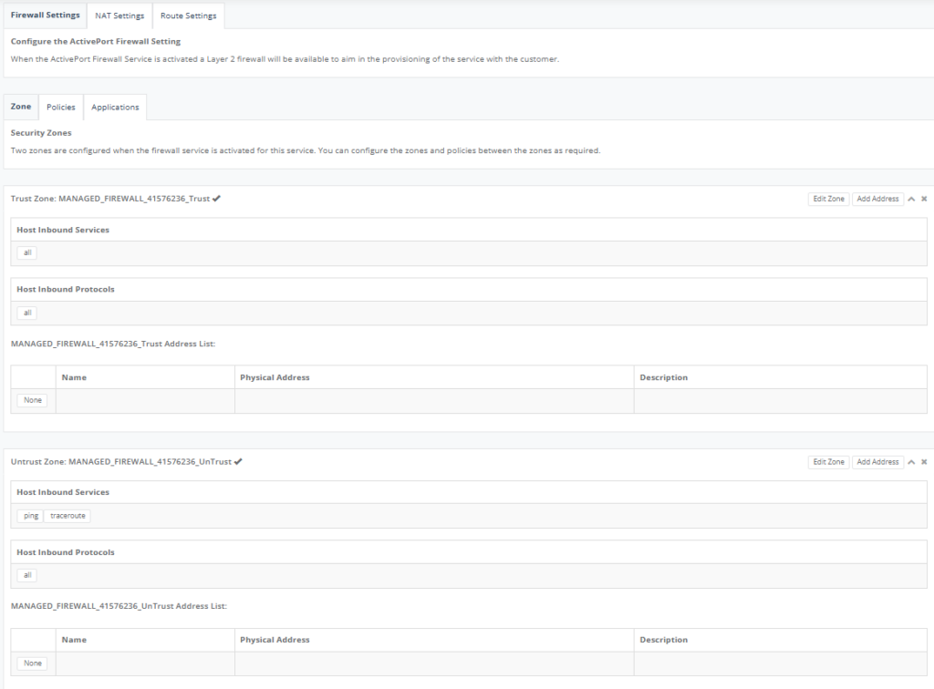
Step 17: Click on “Firewall Setting” Tab, click on “Zone” Tab to configure Trust & Utrust Zone.
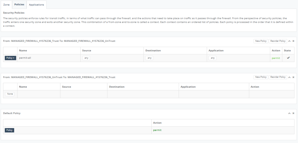
Step 18: On “Policies” Tab to configure enforce rules for the transit traffic.
Step 19: On “Applications” to configure permit/deny application.

This user guide will demonstrate how to configure a DC-DC link. View the YouTube Link.
Pre-requisites
– User shall have username & password to login to GE Portal.
– User has created a network.
– User has created a SD-WAN NTU at the PoP location (say Perth).
– User has created a SD-WAN NTU at another PoP location (say Melbourne).
Step 1: Navigate to “Network Links” tab on the map view.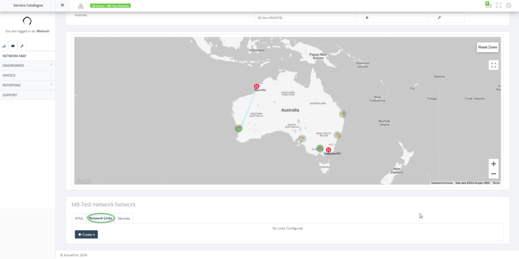
Step 2: Choose DC – Link
Step 2a: There is an alternate way to create the DC LINK via the map view.
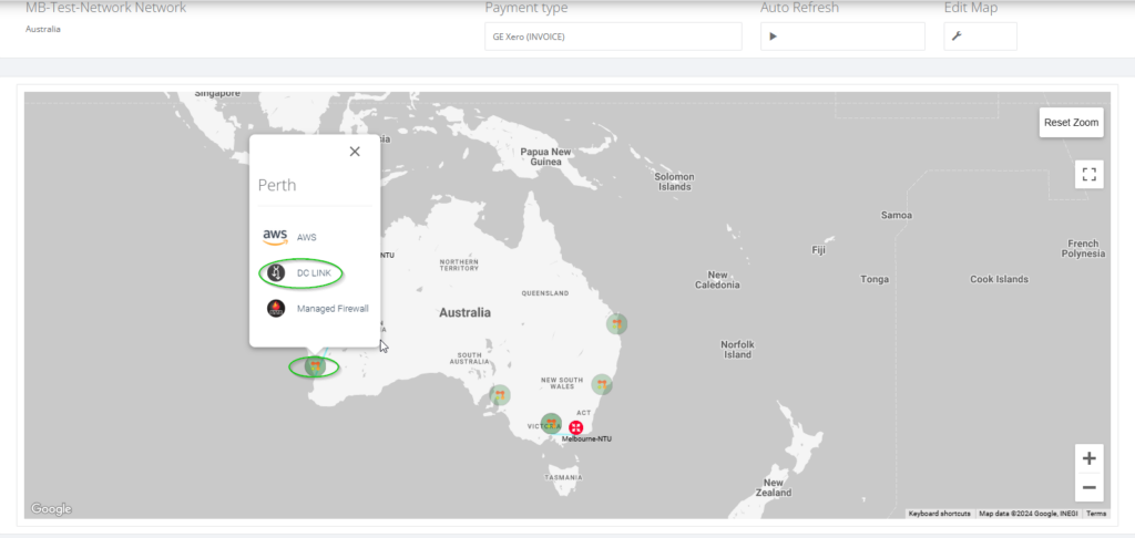
Step 3: Choose the aEnd NTU & bEnd NTU as shown.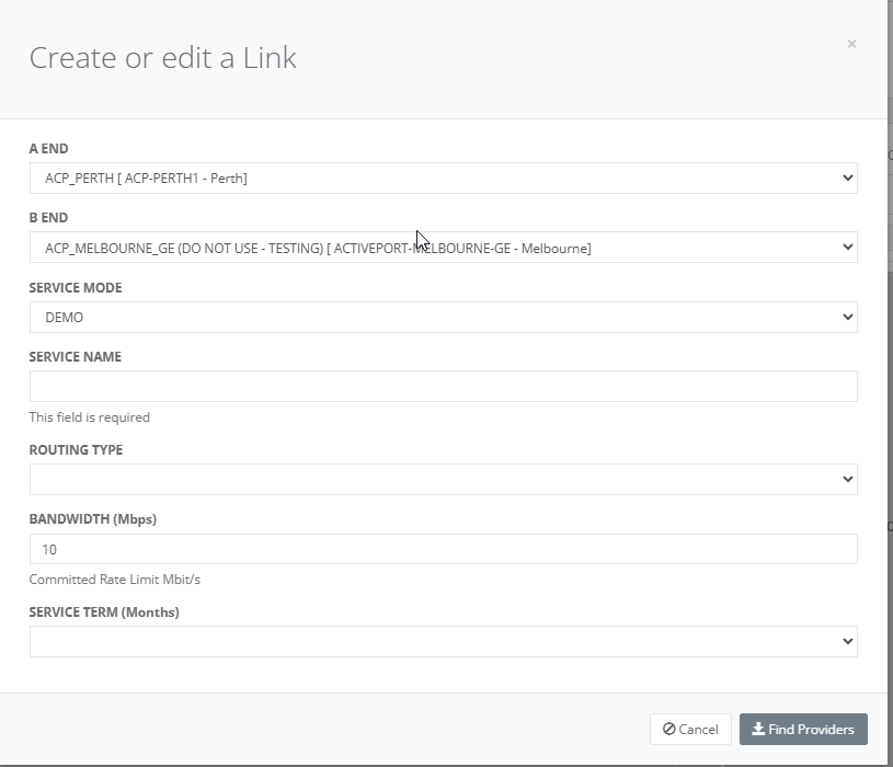
Step 4: Choose the service mode as LIVE.
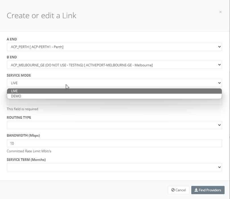
Step 5: Input the name of the DC link (for example: Perth-Melbourne DC link)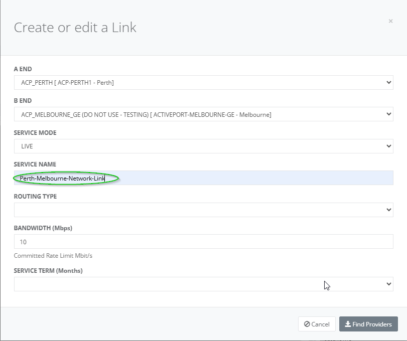
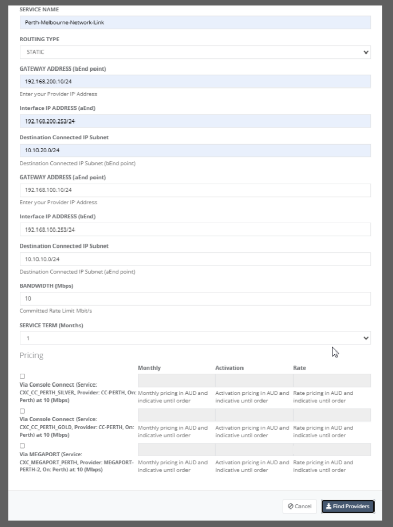
Step 6: Choose the routing type as “STATIC”.
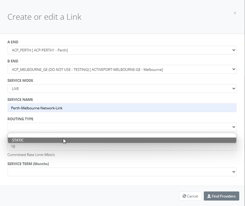
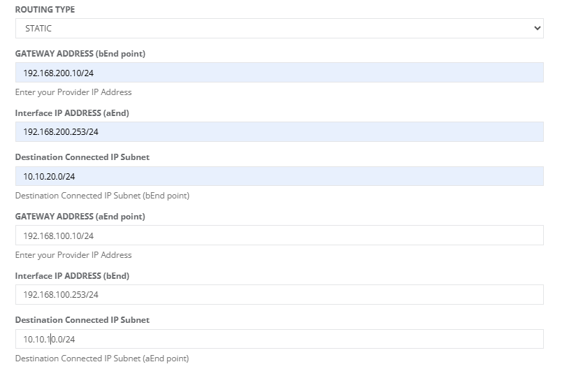
Step 7: For “Routing Type” = “STATIC”, enter the following details:
• bEnd Gateway IP Address
• aEnd IP Address
• bEnd Destination connected IP Address
• aEnd Gateway IP Address
• bEnd IP Address
• aEnd Destination connected IP Address
Step 8: Choose the bandwidth (in Mbps) & the service term.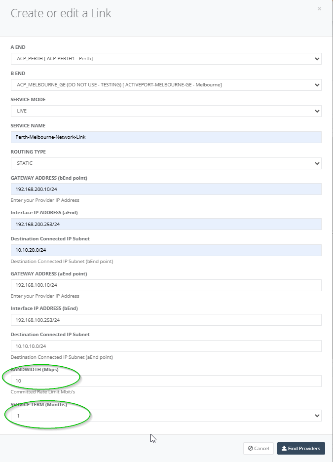
Step 9: On entering all the relevant parameters and on clicking on “Find Providers”, the following providers with the relevant costs are displayed for the user to choose from.
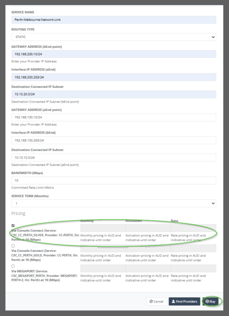
Step 10: On choosing one of the providers (let us say MEGAPORT), the “Save” button is enabled and user can go ahead to save the service configuration details.
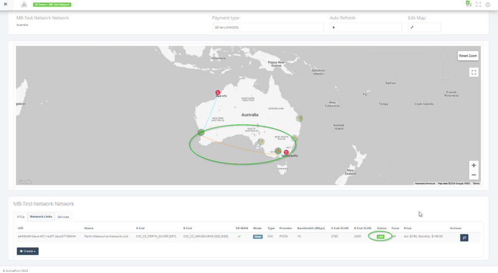
Step 11: Once the details are saved and the operation is successful, the user can view the following in the map.
o A link connecting the two NTUs in the map.
o An entry under the “Network links” tab for the DC link.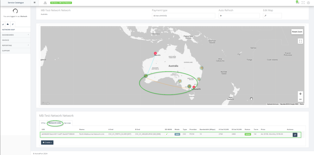
Step 12: Click on “CHANGE STATUS” for the newly created network link as shown.

Step 12a: Choose ACTIVATE ALL for activating the service.
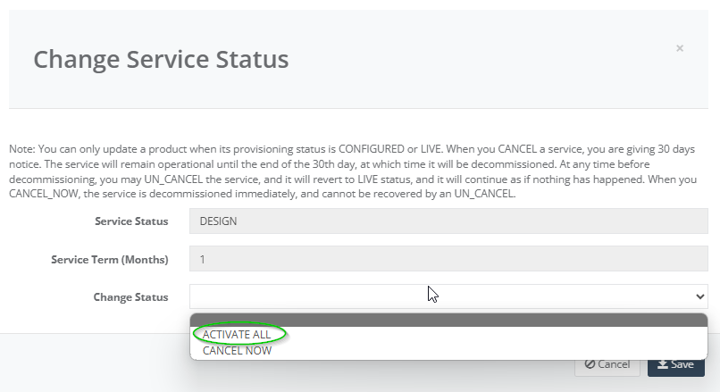
Step 13: The newly created service in LIVE state should be as shown.
This user guide will demonstrate how to configure your Cloud On-Ramp.
Pre-requisites
- User shall have username & password to login to Global Edge Portal.
- User has created a network.
- User has created a SD-WAN NTU at the PoP location (say Perth).
Step 1: Click on the PoP (say Perth) on the network map.
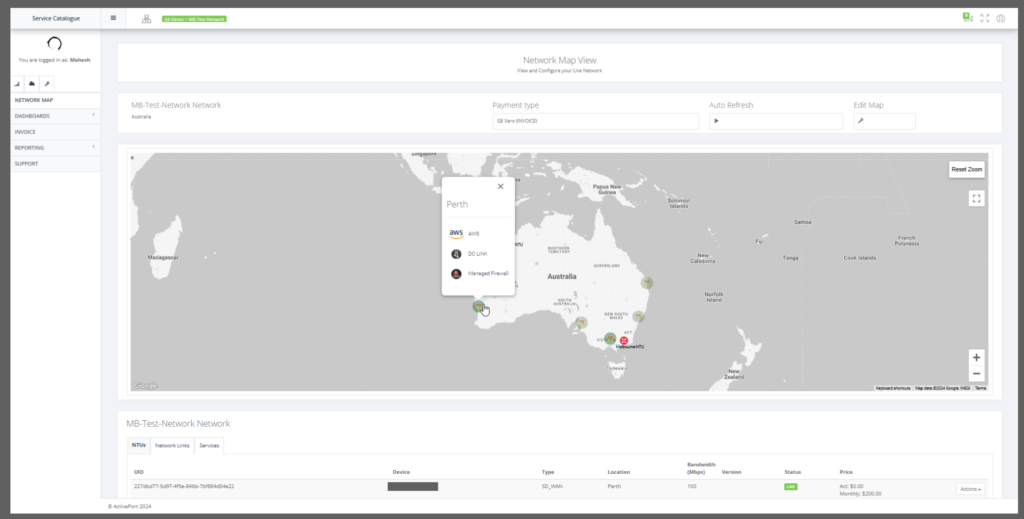
Step 2: Choose AWS option.
Step 3: Select the NTU available at the PoP location.
Step 3: Select the provider either Console Connect or MEGAPORT.
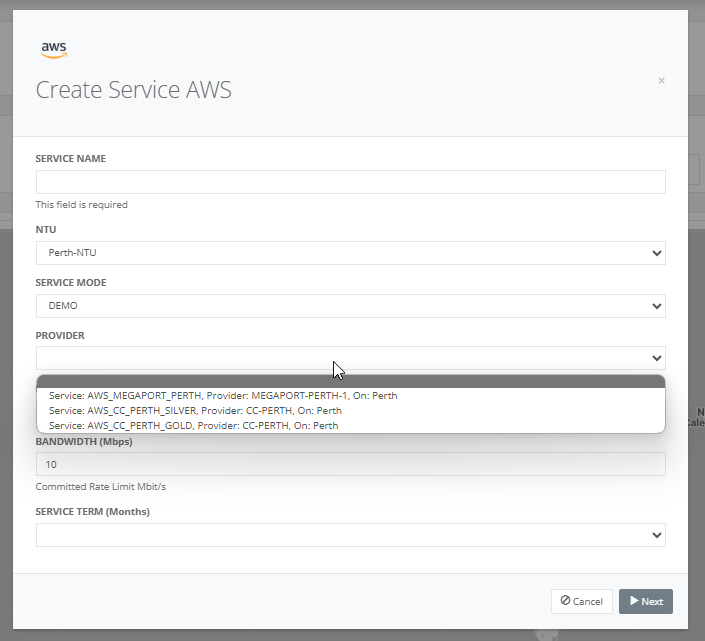
Step 4: On selecting the provider, the list of AWS locations is displayed.
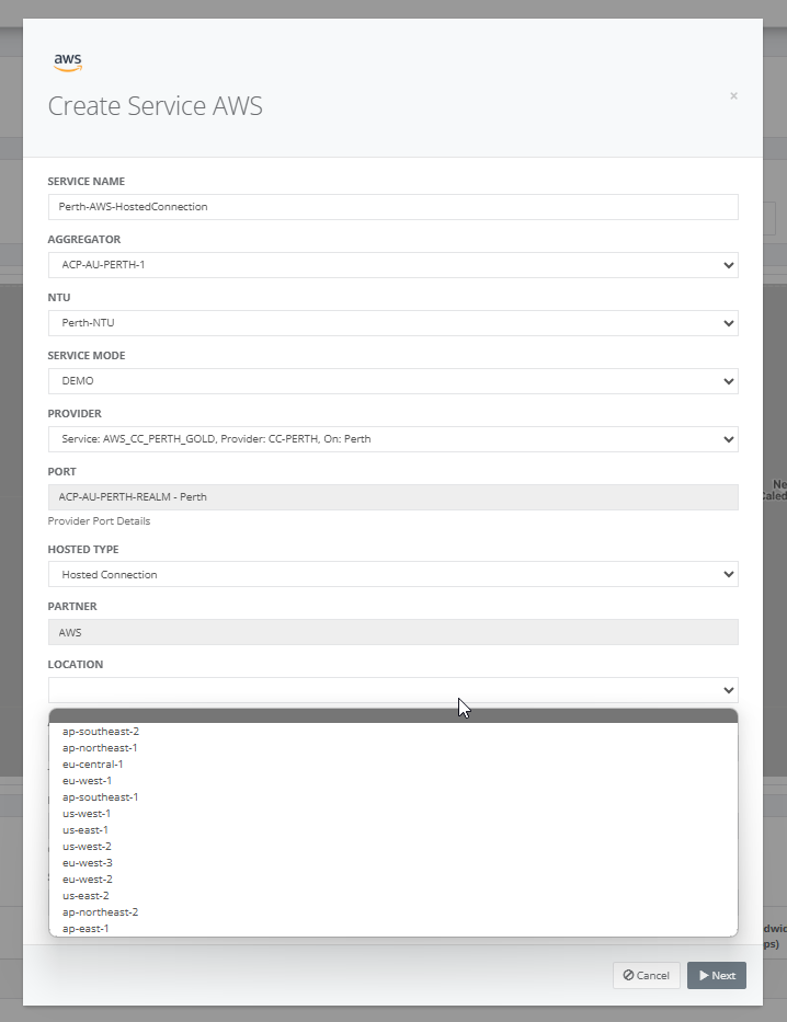
Step 5: Select the AWS location and the list of provider ports are displayed.
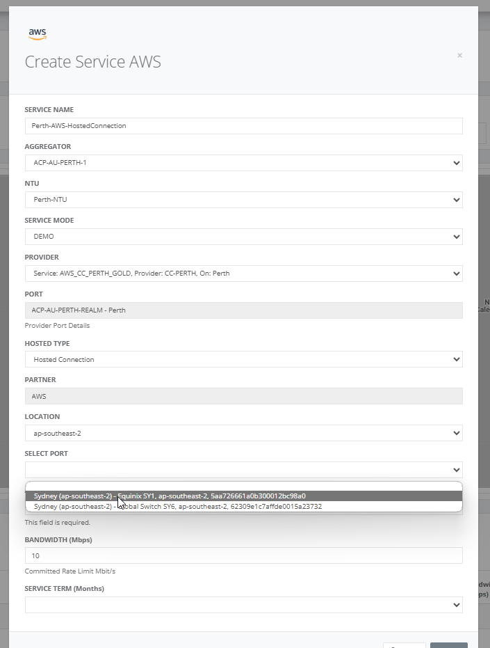
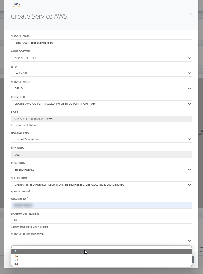
Step 6: After selecting the provider port, enter the AWS account ID, bandwidth and service term.
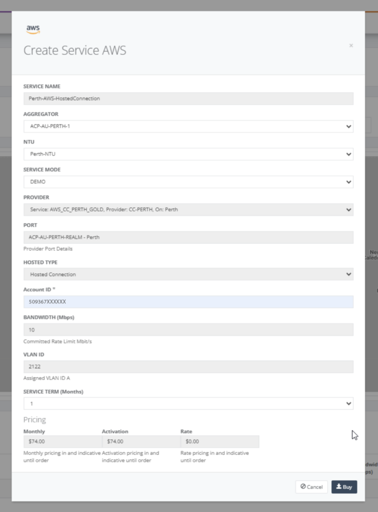
Step 7: On clicking “Next”, the cost for the service is displayed based on the provider chosen.
Step 8: On buying the service, the service is displayed in the view as shown below.
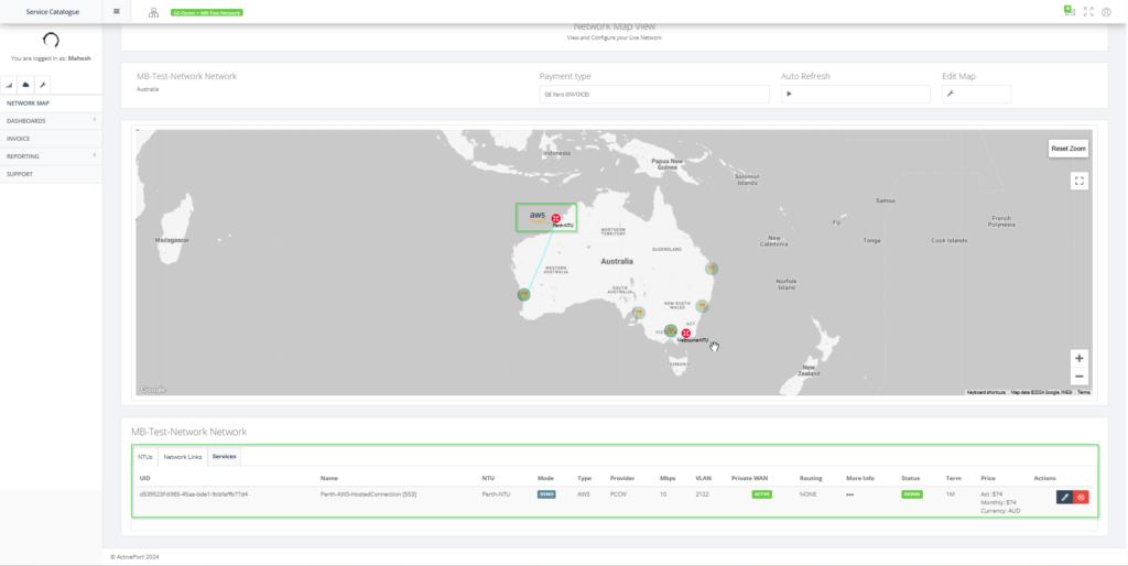
Step 9: After creating the service, it is in “DESIGN” state. Now, the routing details must be added.
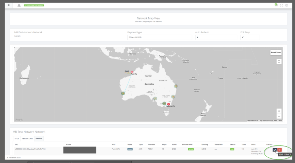
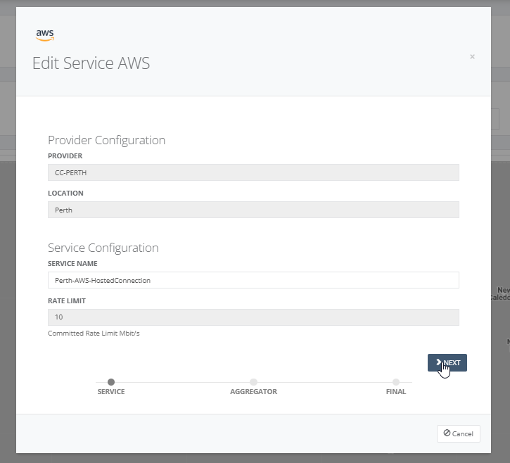
Step 10: By clicking on the “EDIT SERVICE”, the following screen is displayed. Click on “NEXT” to move to the routing details screen.
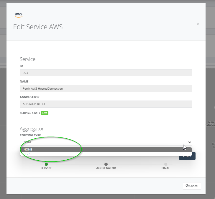
Step 11: Select BGP as the routing type
Step 12: Enter the details such as the
- Customer ASN
- PROVIDER WAN IP ADDRESS
- PROVIDER GATEWAY IP ADDRESS
- Copy the BGP AUTH KEY for later use.

Step 13: Review the details of the service.
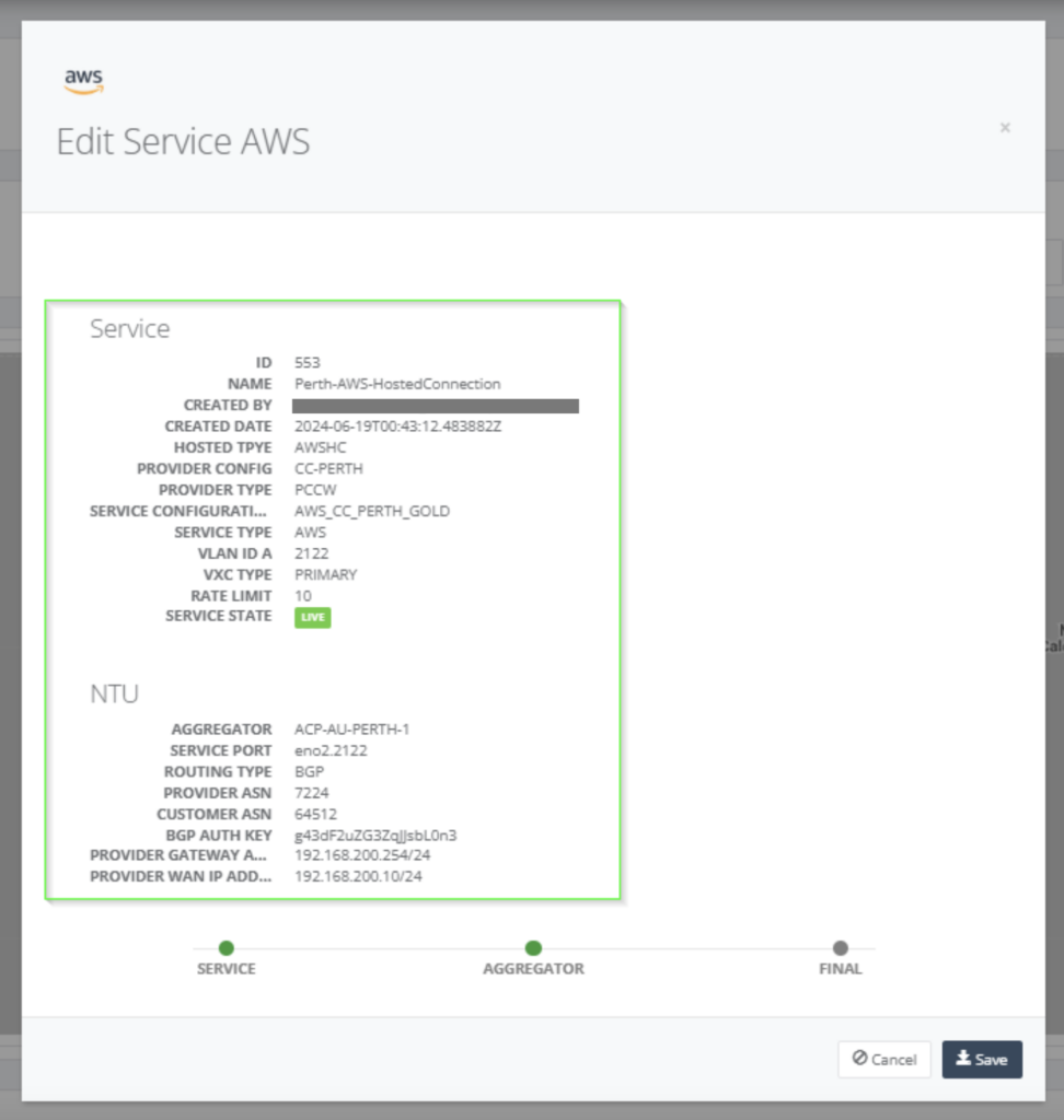
Step 14: Click on “DESIGN” and select “ACTIVATE ALL” for the service updated.
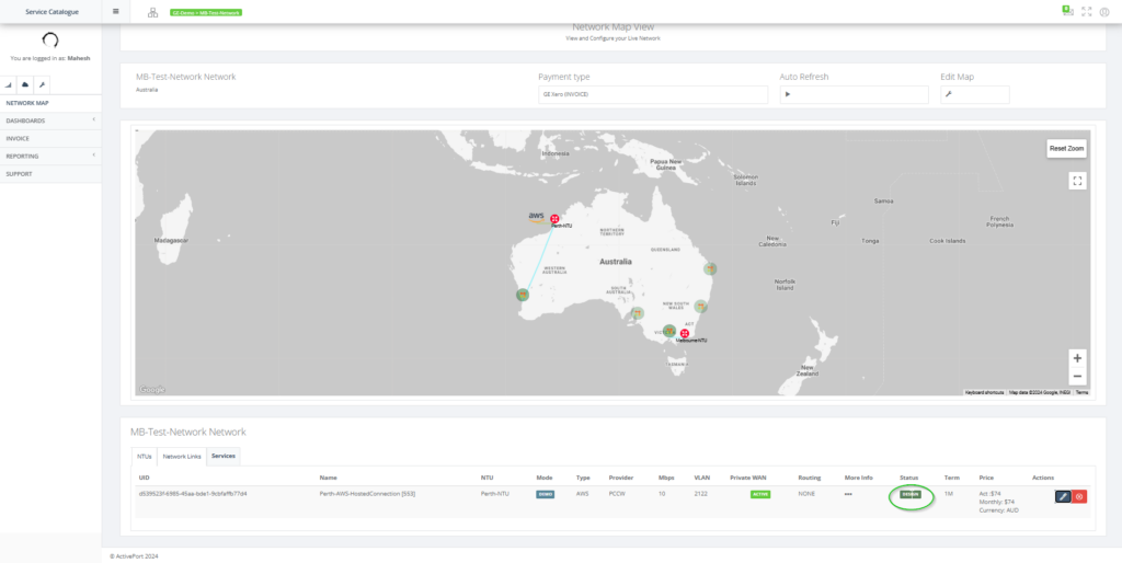
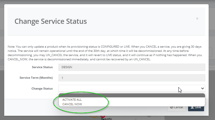
Step 15: After activation, the service is in “LIVE” state.
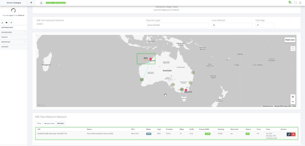
AWS configuration
Step 16: Login to the AWS Portal using the credentials for the AWS account ID entered in the service.

Step 17: Accept the pending AWS hosted connection.
Step 18: Create VIF using the above accepted hosted connection with the details added for the service in Global Edge
- Customer ASN
- PROVIDER WAN IP ADDRESS
- PROVIDER GATEWAY IP ADDRESS
- BGP AUTH KEY
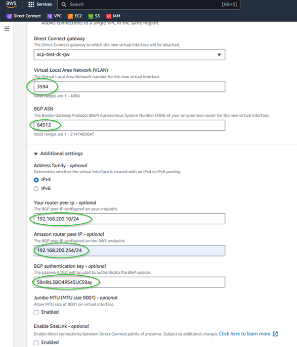
Check for the BGP status to come up.
